Environment umlcomponent#
A component can be defined with the umlcomponent environment:
\begin{umlcomponent}[x=0, y=0]{A}

\end{umlcomponent}


The argument to give is the label of the component. The node representing the state has a default name, based on a global counter. For practical reasons, you can rename it with the name option.
You can also define the width of an empty component with the width option (8ex by default).
You can define a component in another component or in a package. Then, the coordinates of the sub-component are relative to the parent component or package:
\begin{umlpackage}{p}
\begin{umlcomponent}{A}
\begin{umlcomponent}{B}
\umlemptyclass{D}
\end{umlcomponent}
\begin{umlcomponent}[x=4, y=-2]{C}

\end{umlcomponent}
\end{umlcomponent}
\end{umlpackage}
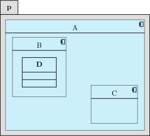
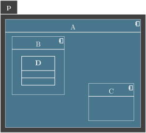
Notice that you can define a class inside a component.
If you want to define a component without detailing it, you can use the \umlbasiccomponent command, that is an alias of the umlcomponent environment.
Provided and required interfaces of a component#
On a component, you can define 2 kinds of interfaces: provided interfaces and required interfaces. For that purpose, you can use umlprovidedinterface and/or umlrequiredinterface commands.
These 2 commands offers the same list of options:
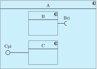
\begin{umlcomponent}{A}
\umlbasiccomponent{B}
\umlbasiccomponent[y=-2.5]{C}
\umlrequiredinterface[interface=Bri, distance=2cm, width=2em]{B}
\umlprovidedinterface[interface=Cpi, distance=3cm, with port]{C}
\end{umlcomponent}
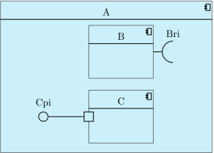
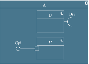
The interface option is used to give the label of the interface, written above the interface symbol.
The interface symbol is a node named X-Y-interface, where X is the name of the component, and Y is west for a provided interface and east for a required interface.
You can change these default names with the {tt name} option.
The width option is used to size the interface symbol. The default value is 1em.
The distance option is used to set the distance between the interface symbol and the component port.
The with port option is used to draw the port symbol.
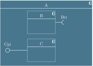
If you look at the previous example, you can notice the padding between the interface symbols on sub-components, and the boundary of the parent component. You can change it with the padding option. The default value is 1cm.
\begin{umlcomponent}{A}
\umlbasiccomponent{B}
\umlbasiccomponent[y=-2.5]{C}
\umlrequiredinterface[interface=Bri, distance=2cm, padding=2cm]{B}
\umlprovidedinterface[interface=Cpi, distance=3cm, padding=0cm]{C}
\end{umlcomponent}
This option will be very useful when you draw connectors.